Attenuators
What a Variable Attenuator Does in a Chain
Controlled loss is a design tool, not a defect. This is what the tool is for and what its specification is actually promising.
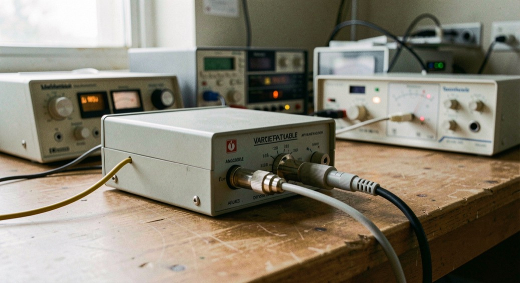
A variable attenuator places a known, adjustable loss between two points of a signal chain. It takes the level the stage before it produces, removes the fraction the engineer commands, and spends the difference as heat in resistive elements. The waveform is otherwise left alone: the part reduces power without appreciably distorting it. Of every block in the chain, this is the one whose effect on the level is chosen deliberately, setting by setting.
Three jobs a controlled loss does well
The first job is protection. A measuring instrument, or the front end of a sensitive stage, can be damaged by the signal levels it meets, and a pad placed ahead of it caps what arrives. The second is leveling: when a signal is too large for an instrument's range, the pad lowers it by a known amount, and a known amount is what makes the reading usable. The third is gain trimming. An amplifier provides gain; an attenuator provides loss, gain below unity, and a chain with too much of the first is put right with some of the second.
The arithmetic is worth internalizing because it is exact, not measured. A 10 dB setting passes one tenth of the power entering it, a 20 dB setting one hundredth, and each 3 dB halves it. The removed power becomes heat, and the dissipation a part survives depends on the mass and surface area of its resistance material, with cooling fins brought in when the package needs help.
What does the attenuator leave alone?
The frequency. A network built only from resistors is linear and reciprocal, and it is not asked to shape the band it sits in: flat frequency response is one of the properties an RF attenuator is specified on, which says plainly that the ideal is one loss across the whole window. A filter selects; this part scales. Reciprocity means the loss reads the same in either direction, and a symmetric pad, built with equal impedances at its two ports, does not distinguish between them: left is called input and right output by convention alone.
Can a pad correct a mismatch?
Not as thoroughly as the word match suggests. The careful wording is that a pad lowers the apparent SWR at a port, and apparent carries the sentence. The impedance step that produced the reflection still exists; what changes is what a source sees when it looks through added loss.
A resistive L-pad can bridge two resistive impedances, but the bridge charges a toll fixed by arithmetic. The minimum loss of a resistive match is 20 log10(sqrt(ρ - 1) + sqrt(ρ)), with ρ the larger impedance divided by the smaller, and it is a monotonic function of that ratio: higher ratios demand higher loss. For a 2 to 1 ratio the floor works out to 7.66 dB, recomputed from the identity rather than taken from a sheet. A passive matching two-port can do the job with less loss, but then it is no longer a resistive pad, and it is not specified like one.
How the loss becomes adjustable
Two mechanisms exist. A stepped attenuator switches between fixed resistances, so its loss moves in defined increments; a continuous one moves along a resistance law, of which the potentiometer is the bench-level example. At radio frequencies the internal network must be precisely matched to hold VSWR down, and the part takes its unbalanced form when it serves coaxial lines. The two control philosophies, voltage variable against digital step, set the character of the rest of the sheet.
Between two states there is a transition, and the transition belongs to switching rather than to attenuation: by convention the move is read over the 10 to 90 percent window, the same window a rise time is read over on any control line.
The columns, and what they leave out
Four properties carry the specification of an RF attenuator: accuracy, low SWR, flat frequency response and repeatability, with nominal impedance, bandwidth and power dissipation alongside. Range is the column quoted first and proves the least on its own. Phase is the quiet one; nothing obliges a sheet to publish a phase figure for an attenuator, so a sheet that carries the column is saying something, and a sheet that omits it is saying something too.
| Column | What it promises | What it does not say |
|---|---|---|
| Range | Every commanded loss between the stated limits exists as a setting. | Whether each setting is flat or accurate across the band; those are other columns. |
| Residual insertion loss | The loss still in the path at the minimum setting. | Its slope with frequency; the part never leaves the chain, it only reaches its floor. |
| Flatness | How little one setting varies over the frequency window. | The window itself, without which two figures cannot be compared. |
| Accuracy | How close a delivered loss is to the commanded one. | The settings and the band points where the tolerance was verified. |
| Phase shift | The phase change through the part at each setting, when carried. | Anything at all when omitted; absence is part of the sheet. |
Where two datasheets stop being comparable
Flatness is quoted over a frequency window, and two figures read over different windows are not the same quantity. Accuracy is verified at chosen settings and chosen points of the band, which the column rarely spells out. SWR appears at both ports or at the more flattering one, and the reflection itself travels under two scales: 20 dB of return loss and 1.22 to 1 of standing wave ratio are one reflection seen two ways. The definitions of flatness, accuracy and monotonicity have a page of their own here, and the units used across this site are gathered in the parameter index.
Before this part goes into the chain
- Measure residual loss at the minimum setting, at mid-band and both edges of the band in use.
- Copy the frequency window beside every flatness figure taken from a sheet.
- Note which settings and which band points the accuracy tolerance covers.
- Check SWR at both ports, not only the better one.
- Return to the same setting after a full cycle and read the loss again.
- Confirm the dissipation of the resistance material covers the power the pad must absorb.
Common mistakes
- Reading range as a promise of performance; it only says the settings exist.
- Treating residual loss as absence; at minimum the part still sits in the chain at its floor.
- Comparing flatness figures read over different frequency windows.
- Expecting the pad to fix a mismatch; it lowers the SWR seen, it cannot remove the impedance step.
- Forgetting that removed power becomes heat in the resistance elements.
Command the minimum loss on the variable attenuator already in the chain, measure what is actually left at mid-band and at both edges of the band in use, and write the three numbers on the label beside the quoted flatness. The next level budget will then rest on a floor measured on this bench, not on the range column of a page.