Section 05
Measuring and Specifying RF Components
Insertion loss, isolation, return loss and VSWR: what each measurement is, how the vector network analyzer produces it, and what connector care changes.
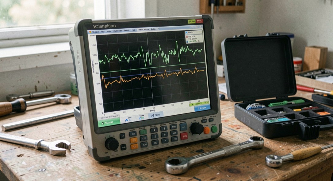
Every column on a control component datasheet is the result of a measurement, and the measurement carries its own uncertainty. A figure quoted to a tenth of a decibel from an instrument that was calibrated on a different day, at a different temperature, through a different adapter, is not wrong so much as unqualified. This section covers what the common measurements are and what has to be true for them to mean anything.
Three pages carry it. Insertion loss and isolation defines the pair that describes a switch. VSWR and return loss gives the exact conversion between the two scales the same reflection is printed on. Calibration and connector care covers the part of accuracy that lives in the hands rather than in the instrument.
Standards, and what they actually fix
Public standards fix some of this and leave the rest to practice. IEEE Std 287 governs the mechanical definition of precision coaxial connectors, which is why a mated pair from two makers repeats at all. The MIL-STD-202 and MIL-STD-883 families define test methods and their conditions, so that a screening line on a datasheet points at a written procedure rather than at a habit. Where a figure is set by convention and not by a standard, this site says so.
The definitions themselves are collected in the datasheet parameter index.
What this section will not print
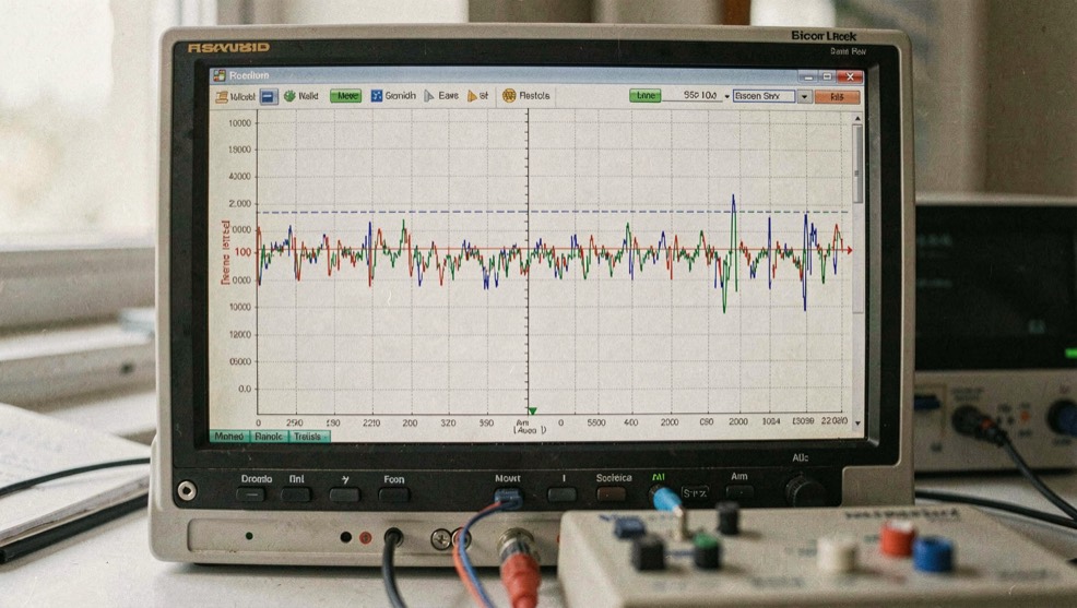
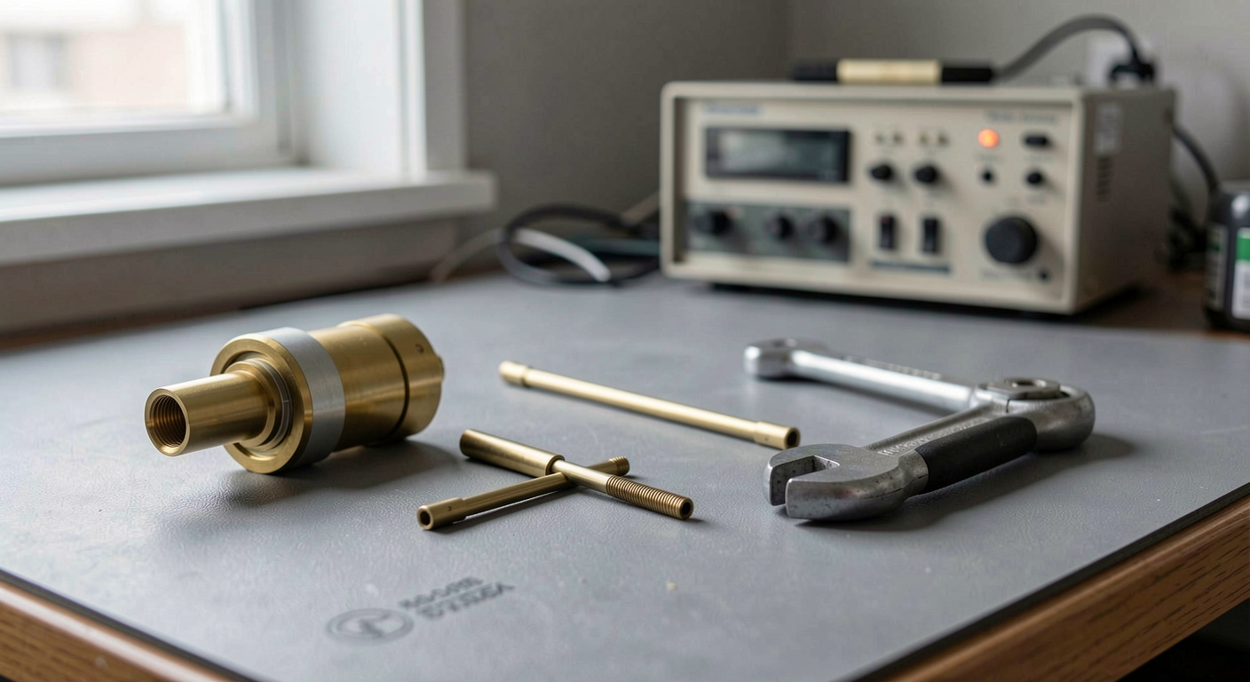
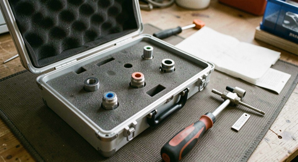
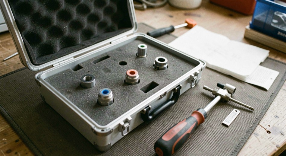
No measurement made here. This publication owns no instruments and takes no readings, so there is no bench data on this site and no page pretends otherwise. Every photograph is an illustrative scene and none of them documents a real instrument reading. What is printed is the definition of the measurement, the quantity it produces, and the conditions that have to hold for the result to mean anything at all.
Where a figure follows from a definition, the arithmetic is shown so that a reader can reproduce it in a minute.
One consequence deserves stating plainly. Because this publication takes no readings, nothing here can be checked against a bench in this building, and nothing here should be treated as a measurement report. It is a description of what measurements are and of the conditions under which their results carry information. A reader who needs a value for a particular device needs that device's own qualified documentation, not a reference page.
The other doors of the publication: Switches, Attenuators, Detectors and DLVAs and Assemblies. Every one of them points back to the datasheet parameter index.
In this section
8 pages, newest first.
-
Insertion Loss and Isolation
One measurement, taken twice: once through the path that conducts and once through the path that blocks.
September 6, 2026
-
VSWR and Return Loss
A ratio and a decibel figure describing the same reflected wave. The arithmetic between them is short and worth doing once.
September 6, 2026
-
Calibration and Connector Care
The instrument is rarely the weak link. A hand tightened connector and a calibration from yesterday are.
September 6, 2026
-
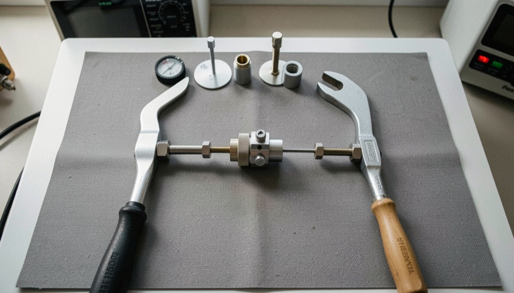
What Bench Instruments Owe to the First Public Terminals
A rack that measures by itself is a small network, and it was not the first one.
September 6, 2026
-
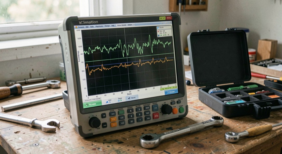
Command Lines and Digital Identity: Address, State, Log
A control line carries three separate things, and digital identity separates the same three acts.
September 6, 2026
-
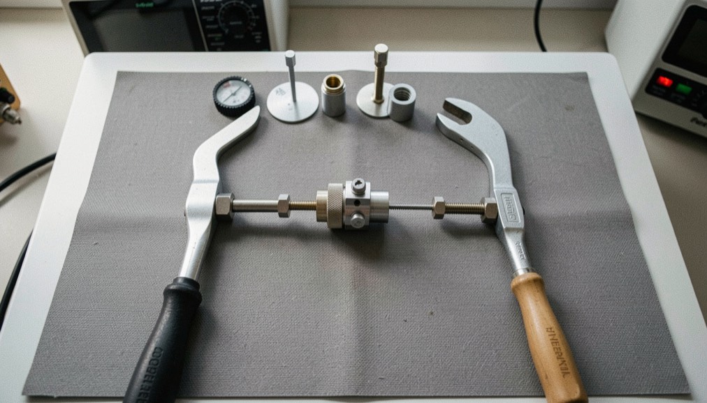
What a Measurement Rack Owes a Homelab
A rack and a homelab share one structure: enclosure, power, internal network, monitoring, and spares.
September 6, 2026
-
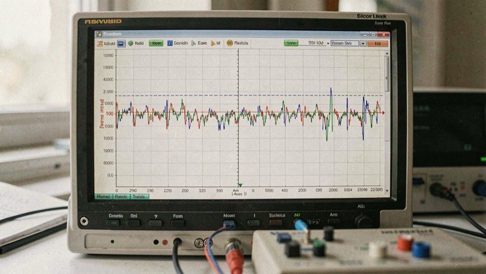
Dated Records for Bench Measurements
A measurement file is only as useful as the reader who can reconstruct it without having stood at the bench.
September 6, 2026
-
What a Calibration Certificate Proves
A certificate documents a comparison chain, not an instrument's accuracy: reference, traceability, range, date, and the limits of what was measured.
September 6, 2026