An independent reference on microwave control components
Control Line Review
A switch, an attenuator and a log detector are sold on one page of figures each. This publication takes that page apart: what every parameter means, how it is measured, and where it misleads.
- 50 Ω Reference impedance The system these parts are specified in
- 1.22 : 1 VSWR at 20 dB return loss One reflection, two scales
- 3 dB The half power point Where a stated bandwidth ends
- 10 to 90 % Switching time window The convention a rise time is read over
These four are definitions and one exact conversion, not measured performance. The VSWR column is computed as (1 + 10^(-20/20)) divided by (1 - 10^(-20/20)), which gives 1.222, recomputed on September 6, 2026. Nothing on this site states the performance of a named product. The same figures are published in the datasheet parameter index.
The five sections
From the component on the bench to the measurement that qualifies it.
-
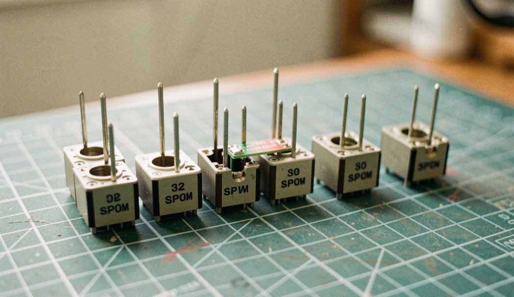
Solid-State Microwave Switches
What the topology decides before any figure on the page does.
Section 01
-
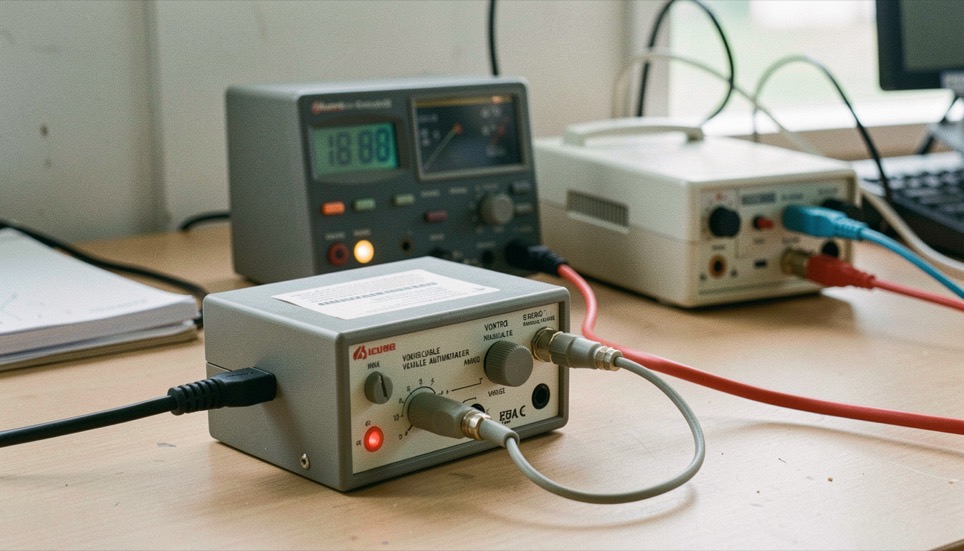
Variable Microwave Attenuators
Range is the easy column. Flatness and accuracy are the ones that decide.
Section 02
-
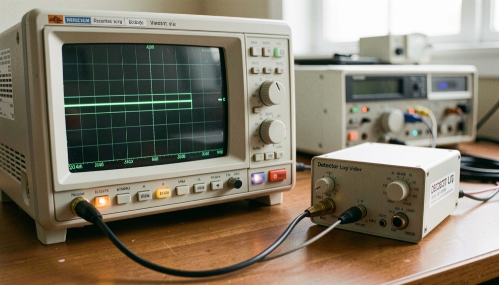
Detectors and Log Video Amplifiers
A curve, not a number: what a log detector actually promises.
Section 03
-
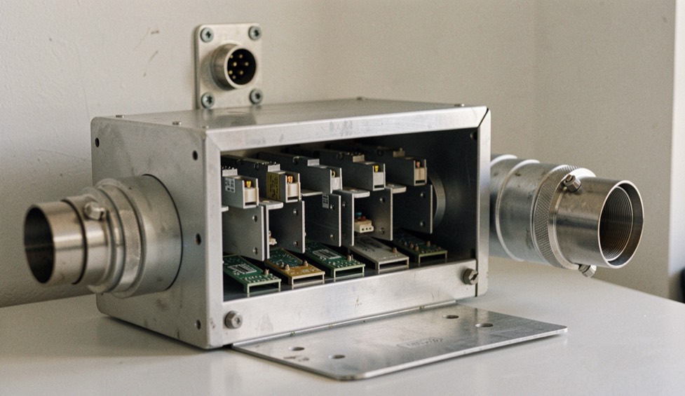
Integrated Microwave Assemblies
One housing, several functions, and a different way of specifying.
Section 04
-
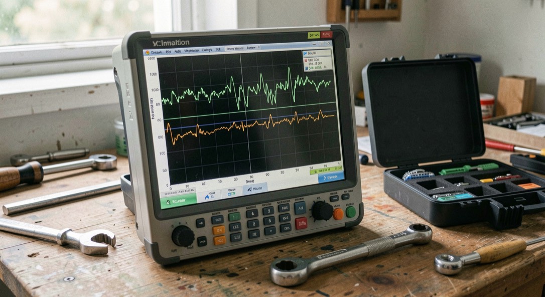
Measuring and Specifying RF Components
Where every number on every other page of this site comes from.
Section 05
The two standing references
Cited by every section, so that no page has to define a term twice.
-
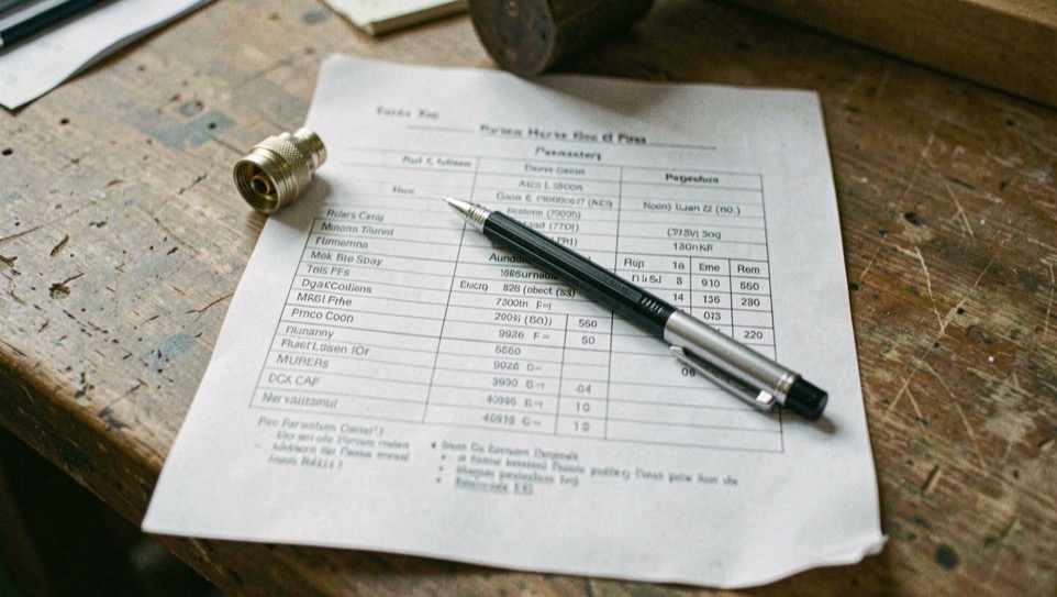
The datasheet parameter index
Definition, unit, measurement and trap, for every column of a control component specification.
Reference
-

Glossary of control terms
The terms a specification uses and never defines, with the confusion each one causes.
Reference
Everything published here
Every page of the publication, newest first.
-
What a Solid-State Microwave Switch Is
Switches
No moving part, one mechanism, and three numbers that come out of it. This is the primer the rest of the switch section is built on.
-
Absorptive and Reflective Switches
Switches
The off port either sends the power back or turns it into heat. That single difference decides what the rest of the chain sees.
-
Switching Speed and the Driver Behind It
Switches
Two parts built on the same diode can be specified very differently in speed. The difference is almost never the diode.
-
What a Variable Attenuator Does in a Chain
Attenuators
Controlled loss is a design tool, not a defect. This is what the tool is for and what its specification is actually promising.
-
Voltage Variable and Digital Step Attenuators
Attenuators
Neither control philosophy is more accurate in general. They fail differently, and a chain is designed around the failure it can live with.
-
Flatness, Accuracy and Monotonicity
Attenuators
An attenuator can be accurate and useless. These three columns describe three unrelated ways of being wrong.
-
What a Detector Log Video Amplifier Is
Detectors and DLVAs
Power in, voltage out, compressed logarithmically. The specification that matters is the shape of the line, not a point on it.
-
Reading a Log Detector Transfer Curve
Detectors and DLVAs
Dynamic range without a logging error limit is not a specification. This is how the two are read together.
-
Tangential Sensitivity and Video Bandwidth
Detectors and DLVAs
These two figures are traded against each other. Read either one alone and two parts with the same range will surprise you.
-
What an Integrated Microwave Assembly Integrates
Assemblies
An assembly is not a bigger component. It is a change of interface, and the specification changes with it.
-
Screening and Qualification Documents
Assemblies
A method number points at a written procedure. It says the described test was passed under the described conditions, and nothing more.
-
Insertion Loss and Isolation
Measurement
One measurement, taken twice: once through the path that conducts and once through the path that blocks.
-
VSWR and Return Loss
Measurement
A ratio and a decibel figure describing the same reflected wave. The arithmetic between them is short and worth doing once.
-
Calibration and Connector Care
Measurement
The instrument is rarely the weak link. A hand tightened connector and a calibration from yesterday are.
-
Why Aluminum RF Housings Specify Electroless Nickel Under Gold
Assemblies
Gold is the surface a finish note names. Nickel is the layer that lets the surface keep its promises.
-
Reading a Detector Plot When the Color Is Gone
Detectors and DLVAs
A curve that lives only in color is a curve that does not survive the photocopy.
-
What Bench Instruments Owe to the First Public Terminals
Measurement
A rack that measures by itself is a small network, and it was not the first one.
-
Command Lines and Digital Identity: Address, State, Log
Measurement
A control line carries three separate things, and digital identity separates the same three acts.
-
Citing a Technical Term Without Its Definition
Attenuators
A cited term carries its label but not its definition, and the gap changes what a document is taken to say.
-
Where a Chain Loses Time: Switch and Video
Switches
Two timing budgets, one arbitration: what a switch and a live video chain each spend before the image exists.
-
Lot Sampling Versus Defect Counting
Detectors and DLVAs
Two measurement scales govern acceptance: defects per unit area and defects per lot, and mixing them distorts both.
-
Design Decisions That Outlive the Toolchain
Assemblies
A stable interface is chosen for what must not change, not for the hardware or software available on the day of the decision.
-
The Cost of a Tighter Tolerance
Assemblies
How a narrower specification converts into test hours, screening cost and scrap, and why two suppliers quote the same function far apart.
-
What a Declared Cause Field Can and Cannot Say
Switches
How a declared cause field records an administrative finding rather than a demonstrated physical mechanism.
-
Accuracy Before Speed: A Measurement Session
Detectors and DLVAs
A bench session and a typing drill share one order: configure the station, warm up, hold accuracy, then read speed.
-
What a Measurement Rack Owes a Homelab
Measurement
A rack and a homelab share one structure: enclosure, power, internal network, monitoring, and spares.
-
Dated Records for Bench Measurements
Measurement
A measurement file is only as useful as the reader who can reconstruct it without having stood at the bench.
-
Where the Heat Goes in a Control Component
Attenuators
A control component converts part of the power it handles into heat, and the junction temperature sets the useful limit.
-
What a Calibration Certificate Proves
Measurement
A certificate documents a comparison chain, not an instrument's accuracy: reference, traceability, range, date, and the limits of what was measured.
Four pages to start with
The mechanism, the topology choice, the reflection scales and the detected output.
-
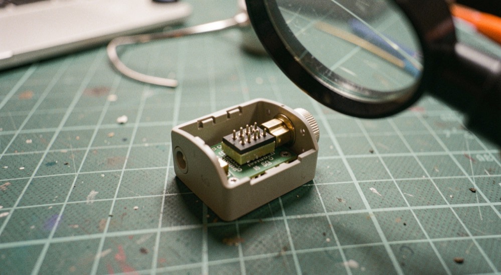
What a Solid-State Microwave Switch Is
No moving part, one mechanism, and three numbers that come out of it. This is the primer the rest of the switch section is built on.
September 6, 2026
-
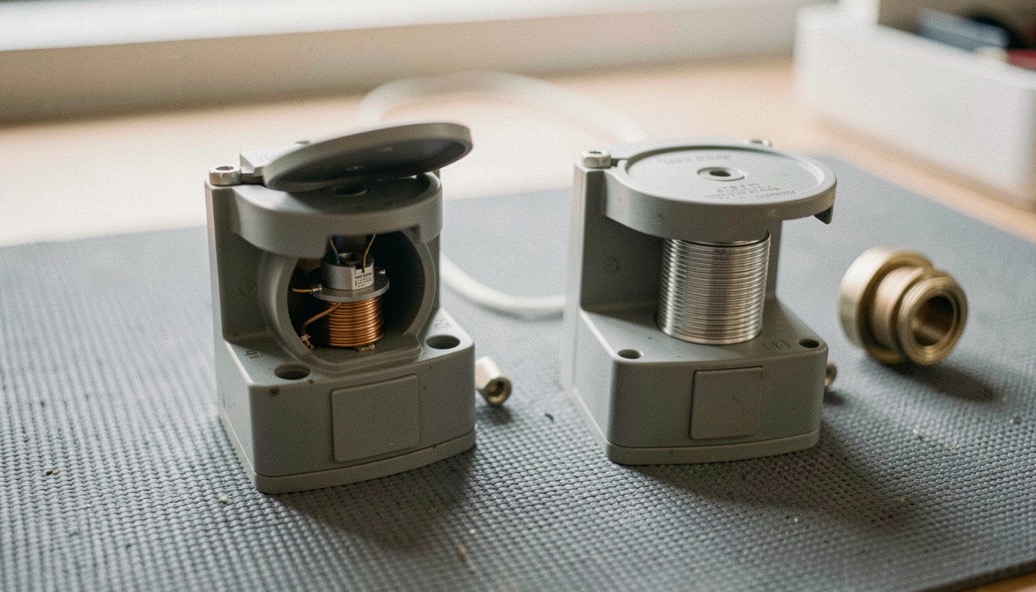
Absorptive and Reflective Switches
The off port either sends the power back or turns it into heat. That single difference decides what the rest of the chain sees.
September 6, 2026
-
VSWR and Return Loss
A ratio and a decibel figure describing the same reflected wave. The arithmetic between them is short and worth doing once.
September 6, 2026
-
What a Detector Log Video Amplifier Is
Power in, voltage out, compressed logarithmically. The specification that matters is the shape of the line, not a point on it.
September 6, 2026
Control Line Review publishes nothing about a named product and holds no commercial relationship with any maker of the parts it describes. How the pages are written, and what is deliberately left out, is on the about page. Where each figure comes from is on sources and method.
The figures we keep qualified
These pages stay on the bench as standing references: definitions, conversions and measurement notes are revisited when the publication changes, so later articles can point to one checked source.
-
Variable Microwave Attenuators
A standing guide to controlled loss, range, flatness and the difference between a voltage command and a digital word.
September 6, 2026
-
The Datasheet Parameter Index
The reference table that gives each figure a unit, a measurement and the question the column leaves unanswered.
September 6, 2026
-
Glossary of Control Component Terms
A plain-language check on the words that specifications use without defining, from absorptive to VSWR.
September 6, 2026
-
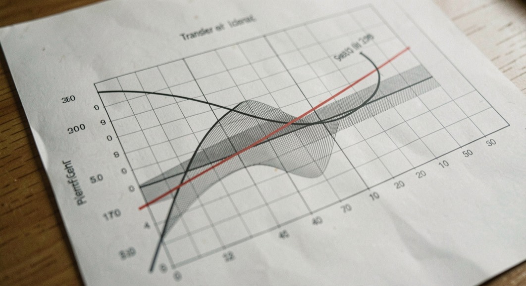
Reading a Log Detector Transfer Curve
A guide to dynamic range, logging error and the transfer line that gives a detector its useful meaning.
September 6, 2026
-
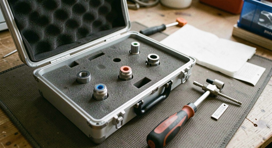
Calibration and Connector Care
The bench routine that puts the reference plane where the measurement can actually be trusted.
September 6, 2026
Along the signal path
These pages carry the desk's habit of careful context into places, bodies, faith, craft and civic life.
-
Reading
St. Petersburg city guide
-
Reading
Plain-English back guidance
-
Reading
Santa Fe reading guide
-
Reading
Traditional Catholic goods
-
Reading
Holy Ascension parish life
-
Reading
Women Lead civic advocacy
Footage licensing, kept entry by entry
A working notebook on clearing moving images, dated where each entry was filed: what a license actually fixes, what it costs, and where archive and newsreel material is held.
Reading
archive footage licensing
Network history, kept as a chronology
A French chronology of applications that live between a browser and a server, kept from the first public announcement of the web in 1991 to service workers and work offline, each entry dated and explained.