Section 02
Variable Microwave Attenuators
Voltage variable and digital step attenuators compared on the terms that matter: attenuation range, flatness, accuracy, monotonicity and control law.
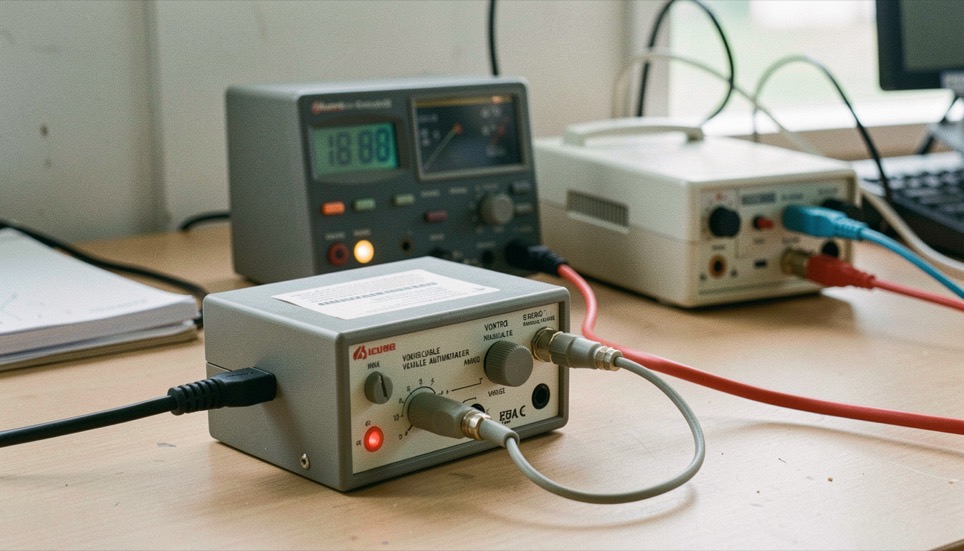
An attenuator that can reach 60 dB is not automatically better than one that reaches 30 dB. Range is the column that is easiest to specify and the least useful for a comparison, because an attenuator is almost never used at its maximum. What a signal chain actually needs is a known attenuation at a known control setting, repeatable across the band and across temperature, and that is a question of flatness, accuracy and control law.
This section takes those columns in order. What a variable attenuator does in a chain is the primer. Voltage variable against digital step sets the two control philosophies side by side. Flatness, accuracy and monotonicity defines the three terms that are constantly used as though they were one.
Control is part of the specification
A voltage variable part is specified against a control voltage, and its transfer curve is neither linear in volts nor linear in decibels unless the maker has shaped it. A stepped part is specified against a digital word and carries a step error instead of a curve. Neither is more accurate in general; they fail differently, and a chain is designed around the failure it can tolerate.
Every term used above is defined once in the datasheet parameter index, with its unit and the measurement it comes from.
What this section will not print
No model, no price, no availability and no supplier advice. The reason is the same one that runs through the whole publication: an attenuation figure only means something with its band, its temperature and its control state attached, and a number lifted away from those conditions invites exactly the wrong comparison. The pages here describe what each column promises and what it quietly leaves out.
Readers looking for a particular part will find the notice at the top of every page more useful than anything written below it.
One last warning about the first column anybody reads. Two specifications that both state sixty decibels of range can behave nothing alike, because one of them reaches that range with a control curve that is unusable over its last twenty decibels and the other does not. Range is a boundary, not a description of the working region, and the working region is what a design lives in.
The other doors of the publication: Switches, Detectors and DLVAs, Assemblies and Measurement. Every one of them points back to the datasheet parameter index.
In this section
5 pages, newest first.
-
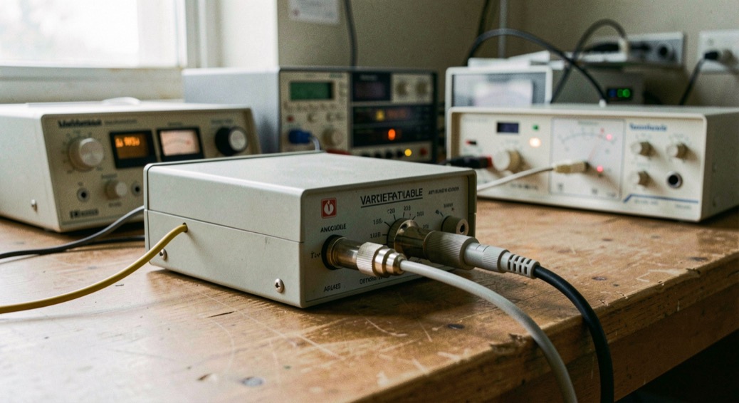
What a Variable Attenuator Does in a Chain
Controlled loss is a design tool, not a defect. This is what the tool is for and what its specification is actually promising.
September 6, 2026
-
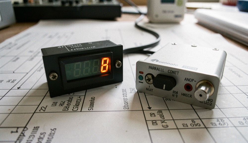
Voltage Variable and Digital Step Attenuators
Neither control philosophy is more accurate in general. They fail differently, and a chain is designed around the failure it can live with.
September 6, 2026
-
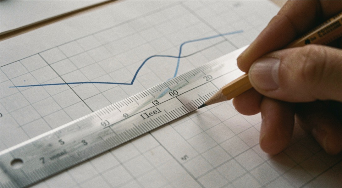
Flatness, Accuracy and Monotonicity
An attenuator can be accurate and useless. These three columns describe three unrelated ways of being wrong.
September 6, 2026
-
Citing a Technical Term Without Its Definition
A cited term carries its label but not its definition, and the gap changes what a document is taken to say.
September 6, 2026
-
Where the Heat Goes in a Control Component
A control component converts part of the power it handles into heat, and the junction temperature sets the useful limit.
September 6, 2026