Assemblies
What an Integrated Microwave Assembly Integrates
An assembly is not a bigger component. It is a change of interface, and the specification changes with it.
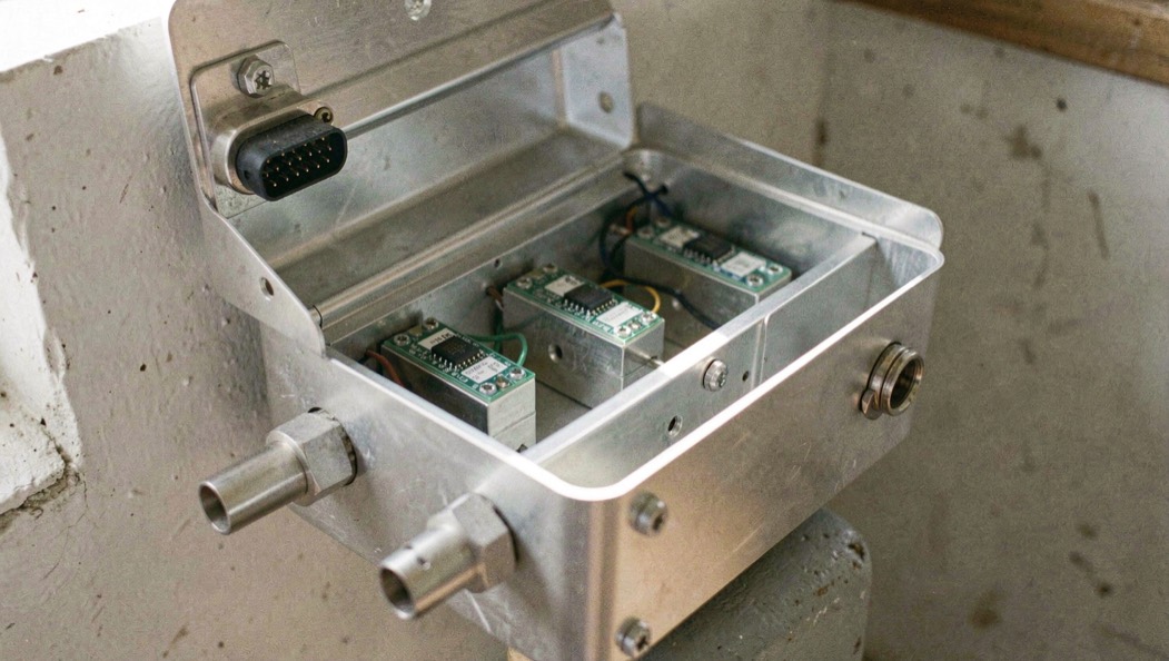
An integrated microwave assembly puts several control functions in one housing: a switch path, an attenuator section, a detector with its log video amplifier, and the drivers that command all of them. It also integrates the joints between those functions. What replaces a chain of boxed stages carries a single command interface, fewer radio frequency ports, and no internal connector left to specify.
What goes into the housing
The short answer is a substrate. A hybrid construction bonds the bare elements to a common substrate and treats the result as one component, and when a sub-assembly is announced as built to a hybrid standard, the reference behind the phrase is MIL-PRF-38534, the performance specification for hybrid microcircuits.
More than the signal chain moves in. The drivers that bias the switching diodes take the bias wiring with them, and the internal terminations that hold a blocked port near the 50 ohm reference impedance settle into the layout. The switch inside it is described in the switch primer, and the attenuator inside it is described in the attenuator primer. What the wall of the housing exposes is no longer a set of bias points but an interface: logic levels compatible with TTL or CMOS, current command, or complementary command. The interface type belongs to the specification.
Where do the connector losses go?
Each joint in the old chain did two kinds of harm. Its series loss subtracted from the budget, and since losses in decibels along a cascade simply add, a few joints acted like an attenuator nobody had chosen. Its reflection sent energy back toward the source, and one reflection reads two ways: an interface specified at 20 dB of return loss sits at a reflection coefficient of 0.1, a voltage standing wave ratio of 1.22 to 1.
Integration removes the internal joints, and with them their losses and their mismatches. The removal is structural, not a design effort: the connectors are simply not there, so their contributions are absent from the budget and from the measurement. What remains at the boundary are the ports of the assembly itself, and every reflection quoted on the datasheet belongs to one of those ports.
Is the command interface part of the specification?
It is, and the switching time proves it. Switching speed is set by two things in series: the time carriers take to establish in the switching diode, and the driver that commands it. A driver that must clear the stored charge of a PIN diode needs a reverse current pulse to do it quickly, and a slow driver makes a fast diode slow. Two assemblies built on identical diodes can carry very different specified switching times, because the driver now lives inside and is specified with the whole.
Conditions travel with the command lines. Hot switching, a change of state while radio frequency power is present, stresses the junction far more than cold switching and is a stated condition of the specification rather than a parameter. The rise time convention, read between 10 and 90 percent of the final amplitude, is a widespread convention rather than a normative requirement, and it applies to what leaves the assembly.
Reading an assembly datasheet
- Read insertion loss as one figure over the whole path, input port to output port.
- Check that isolation is quoted between named ports of the assembly, not between internal functions.
- Identify the command interface, and confirm the stated switching time includes the driver.
- Verify whether hot switching is covered if the state must change under power.
- Read a screening line as a passed test method cited by number, never as a service figure.
One boundary replaces a stack of columns
The datasheet does not shrink; it changes scope. Every quantity once read stage by stage is read once, at the wall of the housing.
| Quantity | Built from boxed stages | Integrated assembly |
|---|---|---|
| Insertion loss | Summed stage by stage, every joint counted | One figure over the whole path |
| Isolation | Per device, between that device's own ports | Between the ports of the assembly |
| Reflections | One at each joint, read as return loss or VSWR | Only at the ports that remain |
| Command | One bias line per driver, wired separately | A single interface, levels in the specification |
| Repair | A failed stage replaced on its own | The assembly replaced as a whole |
| Diagnosis | Stage by stage on the bench | Over the full path, no internal access |
What the bench can no longer separate
When a chain of boxed stages misbehaved, the bench could walk it: measure each stage, find the guilty one, replace it. The assembly removes that walk. Insertion loss is read from S21 of the whole path, isolation as the same quantity on the blocked path, and no probe point exists between the functions. A failure inside the housing is read at the ports, wherever in the chain it sits.
This is the trade integration asks for: fewer joints, one interface and one set of boundary figures, against the loss of stage level diagnosis and single stage replacement. What used to be verified per stage is verified once, on the whole. What the screening line on such a page certifies is in screening and qualification; the short version is that a screening line designates a written test method by number, and the method certifies that the described test was passed in the described conditions, nothing more.
Common mistakes
- Comparing the insertion loss column with a single device's figure; the two cover different paths.
- Rebuilding the old loss budget by adding stage figures; the internal joints no longer exist.
- Assuming isolation between two internal functions equals isolation between two ports.
- Treating the driver as external; its behavior sits inside the stated switching time.
- Expecting to diagnose one stage inside a sealed housing; the bench sees the whole path.
Where the reference plane lands
Measurement gives back some of what integration removed, provided it happens at the right plane. A vector network analyzer reports S parameters for whatever sits between its calibrated ports, and calibration, by short, open, load and thru or by thru, reflect and line, moves the reference plane to the point where the standards were connected. On an assembly that point is the mating face of its own connectors, where the specification applies. Calibration drifts with temperature and with time; an instrument calibrated yesterday is not calibrated today.
Run the check this way: gauge the pin depth of the assembly's connectors before mating anything, torque each joint with the wrench specified for that connector type rather than by hand, calibrate the same day at those faces, then read S21 across the whole path as one number. Compare it with the single insertion loss line of the datasheet, not with any stage figure from the chain it replaced. A tenth of a decibel from a bench whose calibration is not qualified is not wrong; it is unqualified.
The wall itself carries a specification too: an aluminum housing is plated before it is ever sealed, and what the two metal layers on it are for is set out in electroless nickel under gold.