Switches
Switching Speed and the Driver Behind It
Two parts built on the same diode can be specified very differently in speed. The difference is almost never the diode.
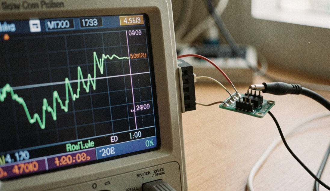
A switching time is set by the driver as much as by the diode. The semiconductor decides how much stored charge has to move; the driver decides how fast that charge moves out. Two assemblies built on the same diode can therefore be specified very differently in speed, and the reason usually sits on the control side of the part. A speed figure describes a pair, and it is read through a convention about where a rising edge begins and ends.
The charge that has to move
A solid-state switch has no moving part. It carries a semiconductor junction between a low impedance state, where the signal passes, and a high impedance state, where the signal is blocked. Above roughly 100 MHz the most common control component for that job is the PIN diode, whose intrinsic layer stores charge carriers. Past its transit frequency, that layer makes the diode behave as a resistor controlled by a DC current, not as a rectifier, and that is what allows an RF signal to be switched without being detected.
Forward bias fills the layer and leaves a low series resistance. Reverse bias empties it and leaves a small capacitance. The stored charge does not vanish when the command changes state; it has to be swept out through the control terminal, and sweeping it takes a pulse of reverse current. The wider mechanism is set out in the switch primer. What follows is the part of it that decides speed.
What does a ten to ninety percent figure measure?
By convention, a switching time is read between the point where the output reaches 10% of its final amplitude and the point where it reaches 90%. That window is a convention, widespread but not a normative requirement; nothing in the physics forces those two levels. A figure is comparable only when both sides state the window it was read over.
The same reading discipline runs through the whole subject. Return loss and VSWR are two scales for one reflection, and a band edge is a -3 dB point because half power is a definition. Units and definitions of that kind are collected in the parameter index. When a page prints a rise time and stays silent about the window, the silence is part of the figure.
The driver carries the other half of the speed
The driver works in both directions. To turn the diode on, it supplies the forward current that establishes carriers in the intrinsic layer; the more current it can deliver, the sooner the low resistance state is reached. To turn the diode off, it sinks a pulse of reverse current that evacuates the stored charge. Turn-on tracks the forward current available, turn-off tracks the reverse pulse.
This is why a slow driver makes a fast diode slow. The junction may be able to change state in a time far shorter than the figure on the page, and never get the chance, because the charge sits in the layer waiting for a driver that clears it at its own pace. Both figures are honest; each one measures a pair.
| Element in the chain | What it limits | Where the limit shows up |
|---|---|---|
| Intrinsic layer of the diode | How much stored charge must be swept out | The shortest turn-off the pair can reach |
| Driver forward current | How fast carriers are established | Turn-on time |
| Driver reverse current pulse | How fast the stored charge is evacuated | Turn-off time |
| Control interface, TTL, CMOS or current command | How fast the command reaches the driver | Delay before any current begins to change |
| RF power present at the switch | Whether the stated speed applies at all | A condition of the test, not a parameter |
Which control interface does a speed figure assume?
Common control interfaces are logic levels compatible with TTL, logic levels compatible with CMOS, current command, and complementary drive. The type of interface belongs to the specification alongside the speed, and a speed figure quoted without it does not say what produced the edge it describes.
A speed figure quoted without its interface is missing the first link of its own chain. The same diode can present a different edge under a different drive, so the interface is not a footnote to the speed; it is one of the things the speed was measured with.
Hot switching is a condition, not a parameter
Hot switching means operating the switch while RF power is present at its ports. It stresses the junction far more than switching with the RF off, and it is not guaranteed by every part. For that reason it is written as a condition of the specification: the speed figure applies when the switch changes state under the stated RF conditions, and it says nothing about conditions that were not stated.
Read as a parameter, hot switching invites a wrong comparison. Two switches can show the same speed while only one of them carries the stated RF level during the transition. The condition belongs on the same line as the speed, in the same sentence.
Common mistakes
- Reading a switching time as a property of the diode alone; the driver carries half of it.
- Treating the 10% to 90% window as a rule rather than a convention.
- Comparing two rise times read over different windows, or over windows nobody stated.
- Ordering a speed without stating the control interface that has to produce it.
- Assuming hot switching comes with the part; it is a stated condition, and not every part carries it.
- Taking speed as a stand-in for isolation, which is a separate measurement on a separate path.
Reading two speed figures side by side
A comparison is finished when both sides are described by the same four things: drive, interface, reading window, and RF condition. The shortest way to check it is to fill in the same six lines for each figure before putting the two numbers next to each other.
Before comparing two switching time figures
- Write down the forward current and the reverse pulse the driver applies, or note that the page does not publish them.
- Write down the control interface: TTL level, CMOS level, current command, or complementary drive.
- Write down the window the rise was read over, and whether the other page states the same one.
- Write down whether RF power was present during the transition, and under what stated conditions.
- Check that insertion loss and isolation are quoted for the same states the comparison intends to use.
- If a line cannot be filled in, record it as missing instead of assuming a value.
What saves a comparison is leaving the missing lines empty and saying so. A speed figure whose driver, interface and RF condition are unpublished is not wrong; it is unqualified, and it stays unqualified until someone drives the part the way the comparison needs. Ask for those four descriptions, or measure them on the bench, and the two numbers start describing the same thing.