Switches
Where a Chain Loses Time: Switch and Video
Two timing budgets, one arbitration: what a switch and a live video chain each spend before the image exists.
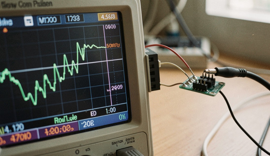
A microwave switch does not close in zero time. The delay between the command at the driver input and a settled RF path at the output is the sum of three intervals: driver propagation, junction rise, and the decision time of whatever instrument declares the event finished. A live video chain spends its time in the same shape, distributed across capture, processing, transport, and projection. The two accounts are not identical, but they are comparable, and the comparison is useful because it separates what a datasheet measures from what a system merely announces.
In both cases the arbitration is the same: latency against stability. A faster edge, a shorter buffer, or a tighter decision threshold buys time and pays for it somewhere else, usually in jitter, in dropped frames, or in a picture that moves before it is ready. The published figures rarely state which side of that trade was chosen. A French-language review of live audiovisual performance and what live transmission does to the image, published as La Mire, treats this same signal chain as its subject matter, including latency arbitration, color bars, and signal processing read as image material, alongside projection geometry and live tape work. Its scope is a reminder that the live video signal chain is a timing problem before it is an aesthetic one.
What follows compares the two budgets term by term, names which quantities are measured under a defined method and which are asserted without one, and identifies what survives a change of hardware.
What does the driver actually contribute?
Driver propagation is the interval between a logic transition at the control input and the arrival of a sufficient bias at the switch junction. It is a property of the driver stage, its supply, and its load, and it is quoted in nanoseconds with a test condition attached: input amplitude, threshold definition, load capacitance, temperature. When the condition is absent, the number is a characterization result, not a specification. The same distinction applies to a camera head or a capture card. A stated capture latency is meaningful only with the resolution, frame rate, interface, and trigger mode named, because each of those changes the pipeline depth. A figure published without them describes a bench setup, not a device.
Rise time, settling, and the decision threshold
Junction rise time is the interval during which the RF path transitions between two defined impedance or attenuation states. It is bounded by carrier lifetime, junction capacitance, and drive current. Settling time extends past the rise: the path must remain within a stated error band, typically expressed in decibels, for a stated duration. The third term is the one most often omitted. Decision time belongs to the measurement system, not the switch. A detector, a comparator, or a frame grabber declares the event complete when its own criterion is met, and that criterion has a threshold, a hysteresis, and an integration window. Two instruments observing the same transition can report different completion times without either being wrong. In video, the equivalent is the point at which a frame is declared valid: at sensor readout, at the end of a processing stage, at buffer commit, or at display refresh. Each declaration is a convention, and the end-to-end latency depends on which one is used as the endpoint.
Where does the video chain spend its budget?
| Stage | Typical interval | What defines the endpoint |
|---|---|---|
| Capture and readout | 8 ms to 17 ms | Sensor integration plus readout, or trigger to first pixel |
| Processing | 1 ms to 33 ms | Filter depth, scaling, and buffer commit policy |
| Transport | 0.5 ms to 16 ms | Link rate, packetization, and receiver jitter buffer |
| Projection | 8 ms to 33 ms | Panel response, scan order, and frame interpolation state |
The table is a budget, not a measurement. Each row contains a range because each row hides a configuration. Capture at 60 frames per second cannot complete in less than one frame period, and readout adds to that. Processing time depends on whether the pipeline is frame-synchronous or line-synchronous. Transport time depends on whether the receiver holds a jitter buffer and how deep it is. Projection time depends on whether interpolation is enabled, because interpolation requires at least one future frame and therefore adds a frame of delay by construction. The sum, not any single row, is the number a performer or a régisseur experiences. Reducing one row without regard to the others can increase total latency if it forces a deeper buffer downstream.
Which figures are measured and which are announced?
A measured figure names its instrument, its bandwidth, its threshold, and its conditions. An announced figure names a benefit. In switch data, propagation delay measured with a 500 MHz probe and a 50 percent threshold is a measurement; a claim of fast switching without a reference plane is an announcement. In video, a capture latency measured from a trigger pulse to a first valid pixel at a defined interface is a measurement; a claim of low latency without a stated endpoint is an announcement. The practical test is whether the number can be reproduced by a third party with different equipment. If the endpoint definition travels with the number, it can. If it does not, the number describes one lab on one day. This is not a criticism of vendors. It is a statement about what a specification is: a contract about a method, not a property of an object.
Common mistakes
- Adding propagation, rise, and decision times from different test conditions and treating the sum as a device specification.
- Comparing a capture latency measured at sensor readout with one measured at display refresh and calling the difference a hardware improvement.
- Reducing processing depth to cut latency while leaving a jitter buffer deep enough to restore the original delay.
- Enabling frame interpolation on a projector and then measuring latency without accounting for the future frame it requires.
- Reading a single stage figure as the chain figure, when the chain figure is what the audience sees.
Chain timing checklist
- State the endpoint of every latency figure: trigger, first pixel, buffer commit, or display refresh.
- Record the instrument bandwidth and threshold used for each timing measurement.
- List the configuration of each stage: resolution, frame rate, interface, buffer depth, interpolation state.
- Sum the stages under one consistent endpoint convention before comparing two chains.
- Re-measure after any change of hardware, because the endpoint convention may not survive the substitution.
- Keep the measurement conditions with the number, so the figure remains reproducible by another party.