Switches
Absorptive and Reflective Switches
The off port either sends the power back or turns it into heat. That single difference decides what the rest of the chain sees.
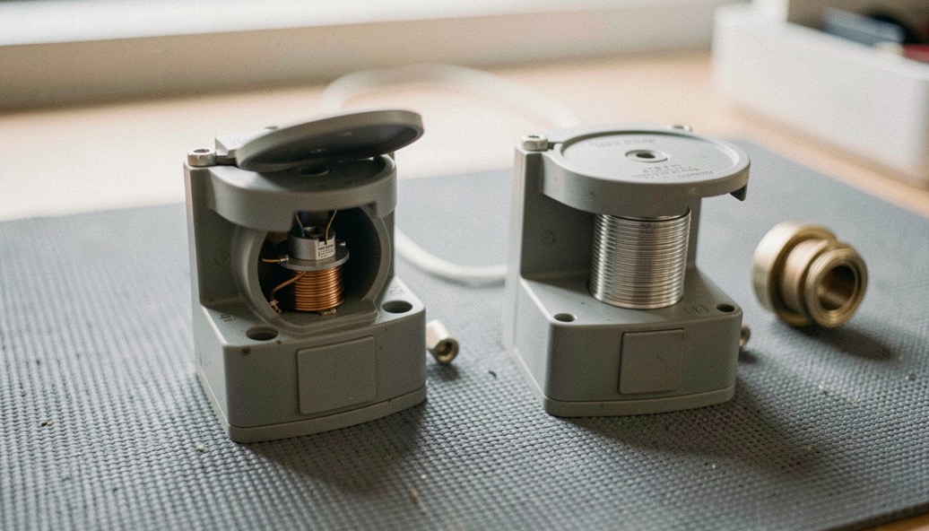
A reflective switch blocks a port by refusing to match it; an absorptive switch blocks the same port and terminates it. The isolation column can read the same figure on both data pages. The difference is where the rejected power ends up: sent back up the line toward whatever drives it, or landed on an internal load and turned into heat. That one difference decides what the switch does to the source, the amplifier, or the mixer standing behind it.
Where does the blocked power go?
The switching element, a PIN diode in most solid-state designs, is not a terminator. Forward biased, it conducts at RF; reversed, it blocks. Neither state is a 50 Ω load, and neither state absorbs. When the element blocks, the port impedance leaves the system value, and a signal arriving at that port splits: part crosses, part reflects. Power that is not accepted travels back; the account stays balanced. The switch primer covers how the element is driven into each state. Both states leave the port far from the system impedance, and the arriving wave reacts before it crosses the first junction.
What the bounced wave does to the stage driving it
The reflection does not stop at the connector. It travels back through everything between the port and the last stage. An amplifier delivering into a reflective port sees a load that changes each time the switch is commanded; what it delivers moves with the control line. A mixer, an amplifier operating with little backoff and a measurement source are the stages a returned wave reaches first, and they are the reason an absorptive design is asked for upstream of them. None of this appears in the switch’s own figures, taken into matched lab gear.
What absorption costs on the through path
The internal termination is bought, not given. The blocked port is loaded by a resistance inside the housing, in general at the value of the reference impedance. More elements then stand between the connectors, so the through path carries more loss than the leanest reflective design; how much more depends on the part and on the band. Complexity rises with the same step: more elements, more bias feeds, more control lines to route and sequence. The exchange is honest: loss and parts count, paid for a port that holds the system impedance in both states.
| Property | Reflective | Absorptive |
|---|---|---|
| Blocked port impedance | Far from 50 Ω, set by the topology | Close to 50 Ω, terminated inside |
| Off-port VSWR | High, state dependent | Low, a designed specification |
| Insertion loss | Lower; fewest elements in the path | Higher; the internal termination adds elements |
| Complexity | Fewer elements and bias lines | More elements, sequenced control |
| Typical placement | Into insensitive or already matched neighbors | In front of sources, amplifiers, measurement paths |
Isolation is one number, the port is two
Isolation is a transmission measurement: how little crosses the blocked path. It says nothing about what comes back, so two parts with equal isolation are not comparable until the architecture is known. The reflection itself is read on two scales, and return loss and VSWR convert one into the other; a port that returns one percent of incident power reads 20 dB of return loss, the same wave read 1.22 to 1 on the ratio scale. What the isolation column never says is where that wave ends up, and the architecture is the only line on the page that answers it.
How much heat can the hidden load take?
Absorption is dissipation. Whatever the port rejects becomes heat inside the housing, and the continuous rating is set by that internal termination; the figure depends on the part, so it is read, never assumed. Feeding a driven source into an absorptive port makes the termination the working load. Hot switching is the harder corner: the junction is stressed far more than when the state changes with the RF off, and whether it is guaranteed at all depends on the part. A reflective design spends little of its own budget here, because the power it refuses stays in the line.
Which architecture belongs on the bench?
The choice follows the neighbor, not the headline figure. In common practice, a stage whose behavior must not move with the switch state, a leveled source, a sensitive amplifier, an oscillator, is fed through an absorptive port. Where the neighbor is insensitive, or the match is provided elsewhere in the chain, the reflective part returns lower through loss for less complexity. The measurement sequence for both figures is set out with insertion loss and isolation; run it with every state commanded before trusting either column.
Bench checks that separate the two
- Measure return loss at the blocked port with the other arm commanded both ways; isolation alone will not reveal it.
- Sweep the whole band; isolation and insertion loss both degrade as it widens, so the edges decide.
- Change state while watching the source power meter; a reading that moves with the command is the blocked port, not drift.
- Find the word absorptive on the data page; a strong isolation figure does not imply a terminated port.
- Check the termination’s dissipation rating before routing a driven source into the port.
Common mistakes
- Comparing a reflective and an absorptive part on the isolation column alone, as though it meant the same thing.
- Assuming every port of a multi-throw switch is terminated when only some arms are.
- Blaming the amplifier for gain that shifts with switch state; the blocked port is pulling it.
- Expecting the isolation column to say anything about the match of the port it describes.
- Routing an oscillator through a reflective port, then chasing the frequency shift elsewhere.
- Treating absorbed power as free; it becomes heat, and the limit is set by the part.
Give the switch already on the bench one afternoon. Terminate every port except the blocked one, sweep its return loss in both states, then re-sweep with the real neighbor in place and watch the source meter through the transition. The result says which architecture was actually bought, and whether the page that promised isolation ever promised a match.