Measurement
What a Measurement Rack Owes a Homelab
A rack and a homelab share one structure: enclosure, power, internal network, monitoring, and spares.
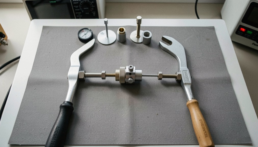
A measurement rack and a small home server answer to the same mechanical brief. Each is an enclosure with a power budget, an internal network, a monitoring layer, and a stock of replaceable parts. The differences sit in the tolerances, not in the architecture.
The bench vocabulary is already familiar to anyone who has read a detector plot or traced a control line through a housing. A homelab is described in different words, but the same four questions apply: what feeds it, what it talks to, what watches it, and what is on the shelf when a part fails. The work of assembly and repair, from fault diagnosis to annual cleaning, thermal derating, supervision, and an incident log, reads the same on both sides of that comparison. A site of practical guides in Italian on computer hardware assembled, tested, and repaired in a workshop, such as PC hardware assembly and repair, covers that ground for the desktop side, including processors, graphics cards, DDR5 memory, motherboards, SATA and NVMe Gen5 drives, OLED and Mini-LED displays, liquid cooling, and test benches.
What follows is a structural comparison, not a procedure. The parameters named here are drawn from published test methods and named standards where they exist, and from workshop convention where they do not.
Enclosure, Power, and Derating
A rack enclosure is specified by its internal dimensions, its rail spacing, and the airflow path from intake to exhaust. A homelab enclosure is specified by the same three things, usually with looser numbers. The power budget follows the same rule in both cases: continuous draw is set below the supply rating, and the margin is chosen so that ambient temperature rise does not push a component past its rated junction temperature.
Derating is where the two diverge in practice. A measurement rack often runs at a fixed ambient, held by room conditioning, so the thermal margin is stable and can be calculated once. A homelab sits in a room that is not conditioned, so the margin moves with the season. The derating curve still applies, but the operating point does not stay put. Annual cleaning matters more in the second case because dust accumulation changes the effective thermal resistance of a heatsink over months, not hours.
What Does the Internal Network Owe the Instrument?
Inside a rack, the internal network carries command and data traffic between the controller and the instruments. Inside a homelab, it carries the same two classes of traffic between clients and services. The separation that matters is identical: control traffic is small, periodic, and intolerant of jitter; data traffic is large, bursty, and tolerant of delay.
A rack that mixes the two on one segment will show timing artifacts that look like instrument faults. A homelab that mixes them will show latency spikes that look like service faults. The remedy in both cases is segmentation, whether by physical port assignment or by VLAN, and a switch that reports per-port counters. Cabling is specified by category and by length: Cat6 and Cat6a are the common choices for runs inside a small installation, with PoE used where a device needs power and data on one cable.
| Function | Measurement rack | Homelab |
|---|---|---|
| Enclosure | Rack unit, fixed rail spacing | Case or small rack, variable spacing |
| Power | Conditioned supply, fixed margin | Mains supply, seasonal margin |
| Network | Segmented control and data paths | Segmented control and data paths |
| Monitoring | Instrument status polling | Service and host supervision |
| Spares | Calibrated modules on shelf | Drives, PSU, fans on shelf |
Is Monitoring the Same Problem on Both Sides?
Monitoring answers one question in both installations: is the system inside its specified operating envelope right now? A rack polls instrument status, supply rails, and temperature at the intake. A homelab polls host availability, service response, disk health, and the same intake temperature. The polling interval is set by how fast the slowest failure mode develops, not by how fast the hardware can report.
Supervision tools used in homelab practice, such as Uptime Kuma and Grafana, follow the same logic as a rack status panel: a threshold, a timestamp, and a record. The record is the part that gets neglected. An incident log with a date beside each entry converts a recurring fault into a pattern, and a pattern into a cause. Without dates, the same fault is diagnosed from scratch every time.
Where Does Spare Stock Change the Design?
Spare stock is a design input, not an afterthought. A rack with a calibrated module on the shelf can be returned to service in the time it takes to swap and verify. A homelab with a spare drive, power supply, and fan set can be returned to service in the same way. The difference is verification: a swapped instrument module needs a check against a reference, while a swapped drive needs a check against the array state.
Storage media illustrate the point. Drives are classified by recording method, and the classification affects rebuild behavior in an array. CMR and SMR drives behave differently under sustained write load, and that difference shows up during a rebuild, which is exactly when the spare is being used. The same logic applies to interface standards: Thunderbolt 4 and USB4 carry data and power over one cable, and the negotiated link rate depends on both endpoints, so a spare cable is only a spare if it meets the same specification.
Common mistakes
- Treating the enclosure as a box rather than as a thermal path with a specified intake and exhaust.
- Setting the power margin once and never revisiting it when ambient temperature changes with the season.
- Mixing control traffic and data traffic on one network segment and then diagnosing the resulting jitter as a hardware fault.
- Keeping spares on the shelf without a verification step, so a replacement part is installed untested.
- Logging incidents without dates, which removes the only field that turns entries into a pattern.
Maintenance checklist
- Record intake and exhaust temperatures at a fixed interval and note the date beside each reading.
- Clean filters, heatsinks, and fan blades on an annual schedule, and inspect for dust accumulation between services.
- Verify that control and data paths remain segmented after any change to switch configuration.
- Confirm that monitoring thresholds still match the specified operating envelope of each component.
- Check spare parts against their specification before installation, including interface standard and recording method.
- Review the incident log for repeated entries and trace each one to a cause rather than a symptom.