Measurement
Insertion Loss and Isolation
One measurement, taken twice: once through the path that conducts and once through the path that blocks.
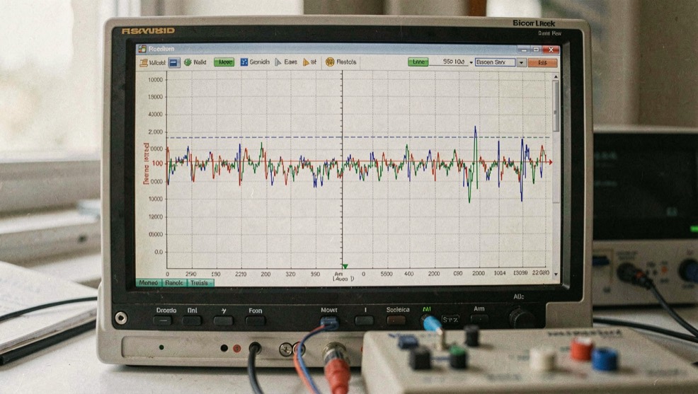
A solid-state switch moves a semiconductor junction between two conditions: a low-impedance state that lets the signal through and a high-impedance state that stands in its way. Insertion loss is the price of the first condition, isolation is the depth of the second; they are not two measurements. Both are -20 log10 |S21|, read once on the path that conducts and once on the path a given state blocks.
One formula, two states of the junction
Above roughly 100 MHz the common control element is the PIN diode. Its intrinsic layer, the I of P-I-N, stores carriers; above a transit frequency the diode behaves as a resistance set by the direct current in its control line, not as a rectifier, and that is what lets it pass a radio-frequency signal without detecting it. Forward biased, it presents a low series resistance and conducts; reverse biased, it presents a low capacitance and blocks.
What does the analyzer actually measure?
The reference instrument, the vector network analyzer, does not read decibels of loss off a part directly. It measures S-parameters: S21 for transmission, S11 for reflection at the input, with S12 and S22 alongside. Insertion loss and isolation are both -20 log10 |S21|, on different switch states; return loss is -20 log10 |S11|. Calibration decides what the figure means: a SOLT sequence, short, open, load, thru, or a TRL sequence, thru, reflect, line, moves the reference plane to where the standards were attached. Calibration drifts with temperature and time, so a unit calibrated yesterday is not calibrated today, and calibration and connector care decide how much of the reading is the part.
| Quantity | Reading it comes from | What pushes it the wrong way |
|---|---|---|
| Insertion loss | -20 log10 |S21|, path engaged | A wider band, cascaded stages, the internal terminations of an absorptive design |
| Isolation | -20 log10 |S21|, path blocked | A wider band; series-shunt topologies exist to win it back |
| Return loss | -20 log10 |S11| | A reflective off state, which returns energy instead of dissipating it |
| Any of the three, as printed | S21 or S11 after calibration | A stale calibration, a dirty connector, hand tightening |
Why both numbers slide as the band widens
Both figures degrade, in general, as the band gets wider, and the reason sits in the two states. The conducting state is not a short circuit but a residual series resistance in the path; the blocking state is not an open circuit but a junction capacitance. Neither impersonation holds across an unlimited span of spectrum, so a junction holding both jobs over a wider band does each less well at the edges. Topology buys margin back: a series diode sits in the path, a shunt diode short-circuits it toward ground, and a series-shunt switch uses both because isolation stacks. Port count changes no definitions; the switch primer takes the topologies in turn.
The blocked path returns the power or absorbs it
Isolation says how little crosses a blocked path, not where the reflected energy ends up. In a reflective switch the extinguished port presents a strong mismatch and the energy is returned toward the source, so the off port runs a high standing wave ratio. In an absorptive, or terminated, design an internal resistor, usually the 50 ohm reference impedance, loads the blocked port and dissipates the energy instead of returning it. A stage sensitive to upstream reflection, a mixer or a measurement source, asks for the absorptive version; the reflective one stays simpler, often cheaper, often better in insertion loss, because it carries no internal loads. The scales convert exactly: 20 dB of return loss is a reflection coefficient of 0.1, a standing wave ratio of 1.22 to 1.
How do the decibels stack in a chain?
Cascade arithmetic is the quiet argument for decibels: losses in dB add, while power ratios multiply. Stages at 1 dB and 2 dB in series cost 3 dB, and 3 dB is the step that, taken at a band edge, defines the half power point. Two 10 dB stages in series cost 20 dB, a factor of one hundred, ten times ten. Integration changes what the arithmetic covers: an integrated microwave assembly specifies insertion loss over the whole path rather than per stage, and its internal connectors disappear along with their losses and their mismatches. What is traded away is the ability to replace one stage on its own; the diagnosis is then made on the assembly as a whole.
A reading is only as good as its reference plane
The analyzer is the easy half of the measurement; connectors are the underestimated half. A dirty mating surface, a coupling that is not aligned, or a connector tightened by hand give poor repeatability, so every mating is torqued with the wrench made for the connector type, pin depth is gauged before a precision standard is mated, and incompatible types are never forced together. Uncertainty belongs to the result: a figure quoted to a tenth of a decibel from a bench whose calibration is not qualified is not false; it is unqualified.
Before the number leaves the bench
- Calibrate the same day, SOLT or TRL, at the plane where the part sits.
- The reference plane sits where the standards were attached, not at the front panel.
- Torque every mating with the wrench made for the connector type.
- Gauge pin depth before mating a precision standard.
- Never force connector types that were not made for each other.
- Record the state, the bias and the band beside both numbers.
Common mistakes
- Calling insertion loss and isolation two measurements; both are one expression read on two switch states.
- Quoting either figure without its band, when both slide as the band widens.
- Comparing reflective and absorptive parts on insertion loss alone; the absorptive one carries internal terminations.
- Adding power ratios where decibels should be added.
- Quoting either figure to a tenth of a decibel from a bench whose calibration is not qualified.
Take one switch to a bench with time to spare. Calibrate at the plane of the part, torque the connectors, sweep S21 twice across the band the system actually uses, once per state, and write the band beside both numbers. Both readings then carry their state, plane and band with them.