Measurement
VSWR and Return Loss
A ratio and a decibel figure describing the same reflected wave. The arithmetic between them is short and worth doing once.
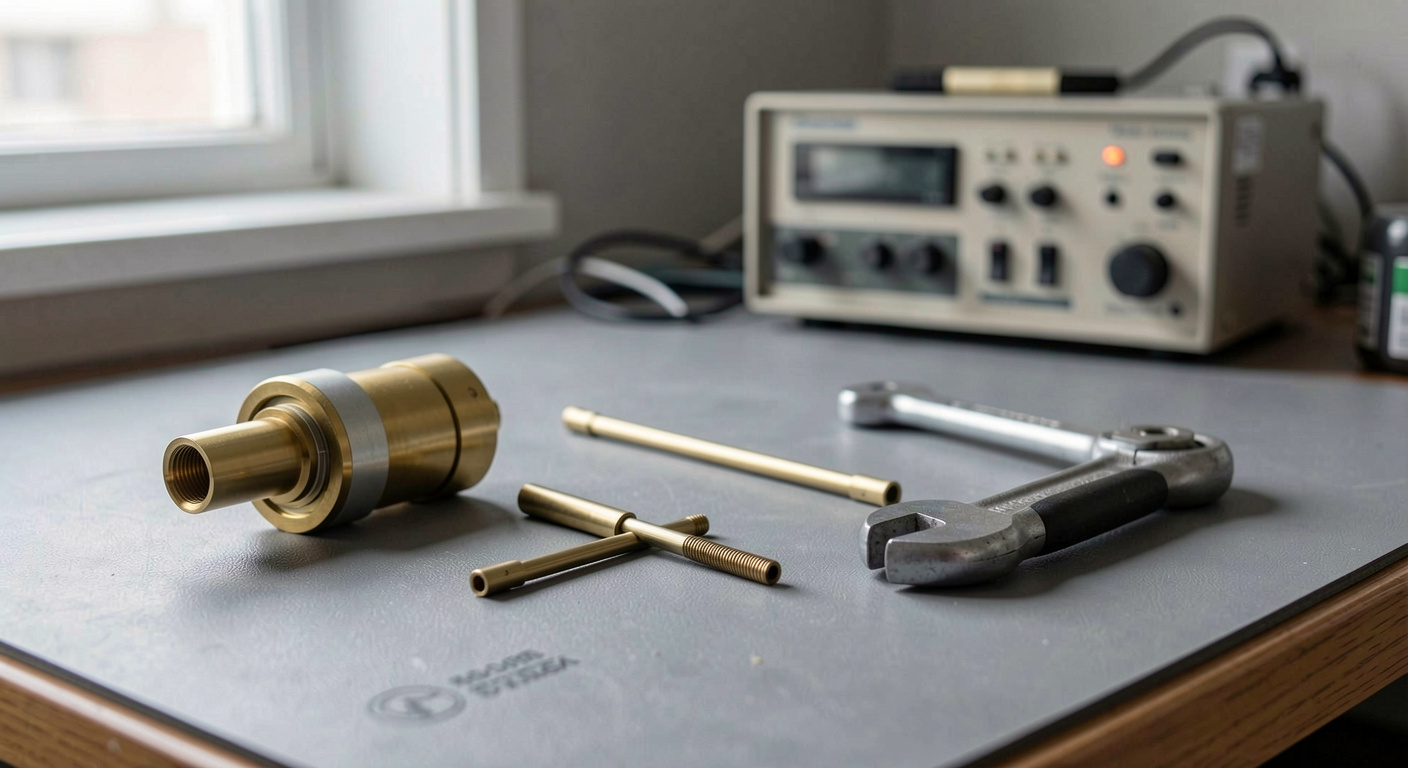
Return loss and VSWR are not two properties of a component. They are two printed scales for one physical event: a port that does not match the 50 ohm reference impedance sends part of the incident wave back. One datasheet states how small the returning wave is, in decibels; another states, as a ratio, how forward and reflected waves add and cancel along it. Twenty decibels of return loss and a standing wave ratio of 1.22 to 1 are the same mismatch computed twice, and the arithmetic between them runs by hand.
Where the reflected wave begins
A port reflects because its impedance differs from the system reference, the 50 ohms of common coaxial practice. When the incident voltage meets that discontinuity, part of it travels back, and the ratio of reflected to incident voltage is the reflection coefficient, Γ, a complex quantity whose magnitude alone, written |Γ|, reaches the datasheet, running from zero, a perfect match, to one, complete reflection. Architecture settles part of the question in advance: a reflective switch leaves its blocked port strongly mismatched and returns the energy, while an absorptive design terminates that port internally, usually at the reference impedance, so the extinguished port stays close to matched. That choice, absorptive against reflective, is made once, before the figures are printed.
How does 20 dB become 1.22 to 1?
The conversion is arithmetic and worth running once by hand. Return loss is defined as RL = -20 log10 |Γ| and stated in positive decibels. Inverting it recovers the coefficient: divide the return loss by 20, change the sign, raise ten to that power. For 20 dB, twenty over twenty is 1, so |Γ| is 0.1, and the reflected voltage is one tenth of the incident one. The standing wave ratio then takes the sum and difference of unity and that coefficient: VSWR = (1 + |Γ|) / (1 - |Γ|). With 0.1, the sum is 1.1, the difference is 0.9, and their quotient is 1.2222, rounded to 1.22 to 1. And since power ratios carry a 10 before the logarithm and voltage ratios a 20, that 0.1 means a hundredth of the incident power returns.
Two formulas, five rows, no instrument
The table evaluates both definitions at five round return loss values. Nothing in it was measured on a bench: every entry follows from the two formulas above, and any reader can check it in under a minute.
| Return loss (dB) | Reflection coefficient |Γ| | VSWR |
|---|---|---|
| 10 | 0.3162 | 1.925 |
| 14 | 0.1995 | 1.4985 |
| 20 | 0.1000 | 1.2222 |
| 26 | 0.0501 | 1.1055 |
| 30 | 0.0316 | 1.0653 |
Read down the columns and the shape of the trap appears. Return loss descends in even steps, but the ratio crowds toward unity: between 20 dB and 30 dB it moves only from 1.22 to 1.07. The decibel scale keeps its resolution everywhere; the ratio spends its digits on gross mismatches and runs out of them where well matched parts live. That compression is not a defect of the ratio; it makes the scale a reading decision before a writing one.
Why do two datasheets disagree?
Set a return loss column beside a VSWR column and the eye reads them as one kind of number. They are not. A part specified at 1.925 and a part specified at 20 dB sit side by side as neighbors, both below two; the table puts ten decibels, a factor of ten in reflected power, between them. Two quieter failures follow. A match figure belongs to a port: the input reflection is S11, the output reflection is S22, and one component seldom shares a number between them, yet a printed line rarely says which port it describes. A value reached at one frequency is not a value held across a band; the page should say which of the two it prints.
What the analyzer is allowed to claim
Each of these numbers arrives through measurement, and the measurement arrives through its calibration. A vector network analyzer reads S11, so return loss is -20 log10 |S11|. The instrument first needs a SOLT sequence, short, open, load, thru, or a TRL sequence, thru, reflect, line, which moves the reference plane to where the standards were attached. Calibration drifts with temperature and time: an evening calibration is not a morning one. Connectors, the underestimated half, supply the rest: a dirty mating surface, a misaligned coupling, a nut tightened by hand, all give poor repeatability, and the wrench made for the connector type is part of the measurement. A match figure quoted to a tenth of a decibel from a bench whose calibration is not qualified is not false; it is unqualified. The rest of that discipline sits with calibration and connector care.
Before trusting a printed match figure
- Identify the scale first; ratio and decibel columns are not comparable until converted.
- Convert both figures to return loss in decibels before judging the gap.
- Ask which port the line describes; S11 and S22 are different measurements.
- Separate a value reached at one frequency from one held across the band in use.
- Recompute one entry with the two formulas as a check on the page itself.
- Take performance values only from the datasheet of the part; they depend on the piece.
Common mistakes
- Comparing a VSWR column with a return loss column as though both were the same kind of number.
- Reading 1.2222 and 1.0653 as neighbors; on the decibel scale they sit ten decibels apart.
- Calling a ratio like 1.925 moderate because it is below two; it is 10 dB, a tenth of the power reflected.
- Assigning one match figure to a whole component when it belongs to one port.
- Quoting a tenth of a decibel from a bench whose calibration is not qualified.
- Calling the conversion approximate; it is exact, and the measurement is the uncertain half.
Take the next datasheet argument to a calculator. From a ratio, recover the coefficient with |Γ| = (VSWR - 1) / (VSWR + 1), then apply RL = -20 log10 |Γ|: 1.925 returns 10 dB, 1.0653 returns 30 dB, and two pages written on different scales become one conversation. Before repeating any of it to a tenth of a decibel, check the calibration date and the torque wrench. The conversion is exact; the measurement never is.